Smart Charger
Smart outlets are essentially plug-in devices. You connect them to a wall outlet or a power strip, and then plug your device into these smart outlets to automate it. This setup doesn’t change the number of available outlets; you’re not gaining or losing any.
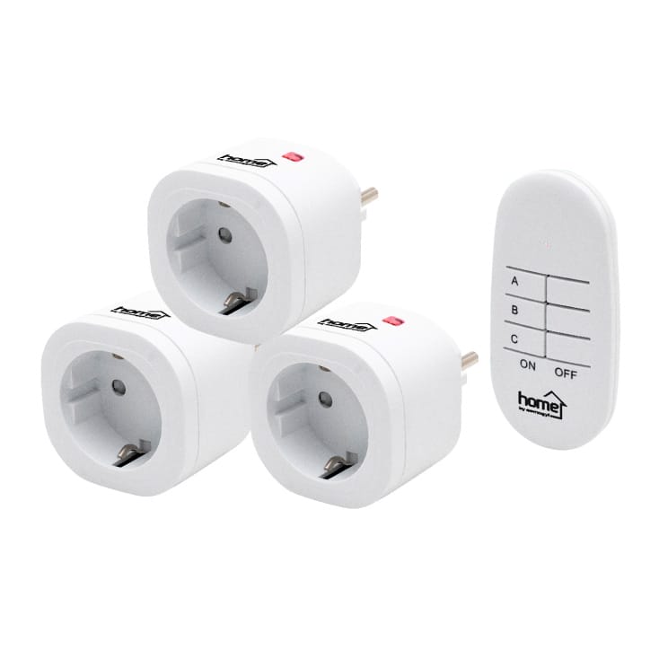
I recently purchased an affordable set of smart outlets for about 26 EUR, which was quite reasonable.
After reviewing the short manual included in the package, I gained a good understanding of their functions and capabilities. In brief, these smart outlets are operated with a remote controller. They are ready to use straight out of the box, so you can manually turn them on and off by pressing the single button on each outlet.
To operate them remotely, you need to assign them to one of three groups: A, B, or C. Any outlet can belong to one, two, or even all three groups. To add an outlet to a group, simply long-press the button on the outlet for 3 to 6 seconds, then release it. If the LED starts blinking, press the corresponding button on the remote controller, and the outlet will become a member of the group associated with that button.
If you want to clear the outlet from its group, long-press the same button for more than 6 seconds and then release it. That’s all you need to know to use the outlets, and they work well with the remote.
However, if you wish to operate the smart outlets without the remote controller, some additional steps are required.
One method involves hacking into the controller, but that’s a destructive and messy approach. A better solution is to intercept the communication between the remote controller and the outlets and reproduce it. For this, you will need an RF 433MHz transmitter and receiver pair, which I purchased as it is quite common.
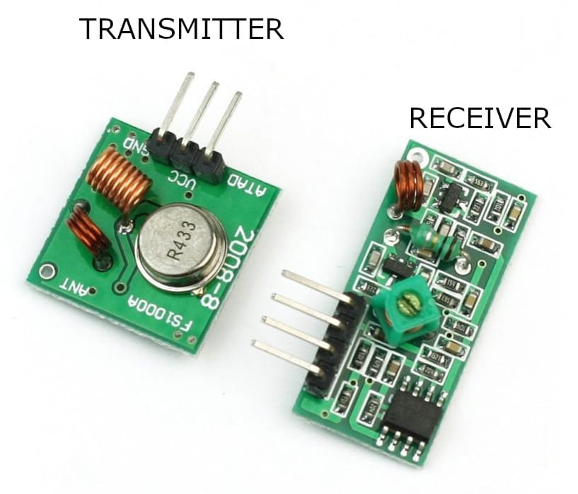
Both components have VCC, GND, and DATA pins (the receiver has two DATA pins, but you only need to use one). They transmit and receive signals in a binary format. You can control the device with a digital output or read input from a digital source.
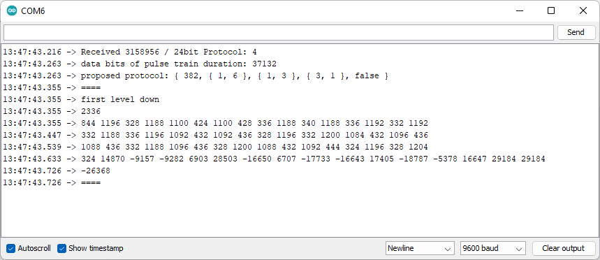
To intercept the communication between the remote controller and the outlets, I used an Arduino with the receiver and the code found in thisGitHub project. This software worked effectively, and I was able to obtain the necessary codes quickly.
| # | ON | OFF |
|---|---|---|
| A | 3158956 | 3985788 |
| 4128620 | 3743276 | |
| B | 4020981 | 3533717 |
| 4174053 | 3811541 | |
| C | 3886478 | 3564062 |
| 3253950 | 3671902 |
Protocol 4, utilizing a 24-bit format, is recognized by the RC Switch library. Each button on the remote controller transmits two codes that change regularly. However, for the smart outlets, only one of those two codes is needed to simulate a button press.
With this in mind, the idea for a smarter smart charger project has emerged.
This upgraded version of the [older project](https://github.com/stonito69/SmartCharger.Server/) addresses a significant design flaw: Bluetooth connectivity can sometimes hang, and without restarting, the connection cannot be reestablished. Since the smart charging functionality relies on this connection, this issue is crucial to resolve.
How does smarter version work?
Hardware is simple and affordable. All this project needs is:
- Raspberry Pi 3B+ version or newer,
- RF 433Mhz transmitter and receiver pair
- Smart Outlet
Raspberry Pi
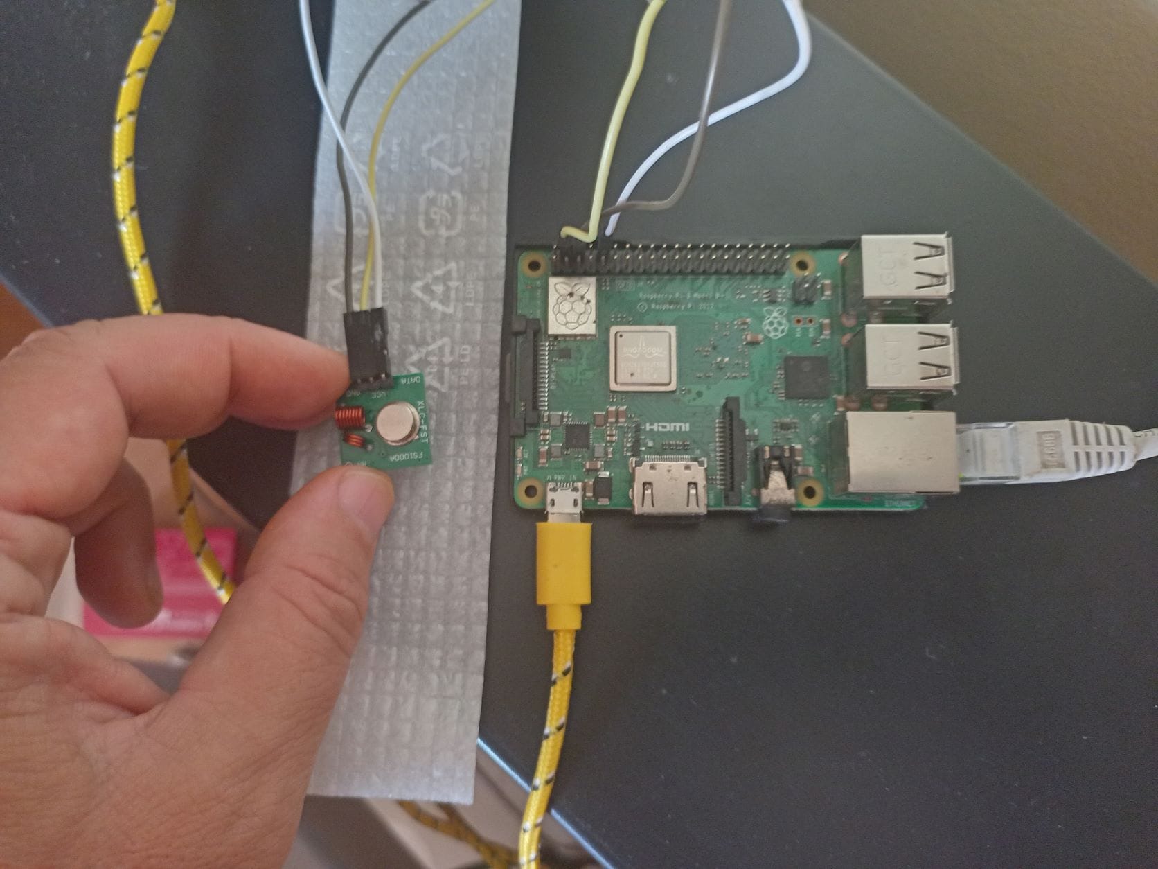
The code for the Raspberry Pi has been written in Python 3 and is available on GitHubWhile the software is straightforward, it functions as a fully-fledged TCP/IP server. It includes logging capabilities and waits for a network connection at boot by pinging the local router before starting. Additionally, it maintains a configuration file that can be updated remotely via a phone app.
Android Software
Software is written in Visual Studio 2022 Community Edition, using Xamarin.
The source code is available on the github.
Application expects running Raspberry Pi from the project above.
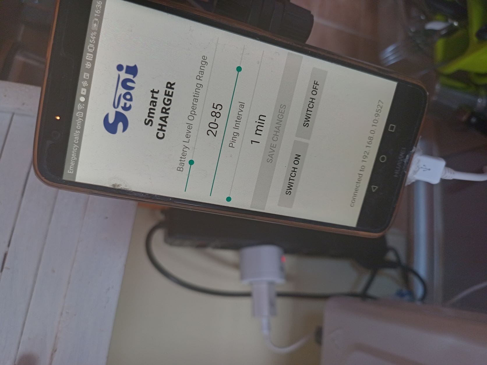
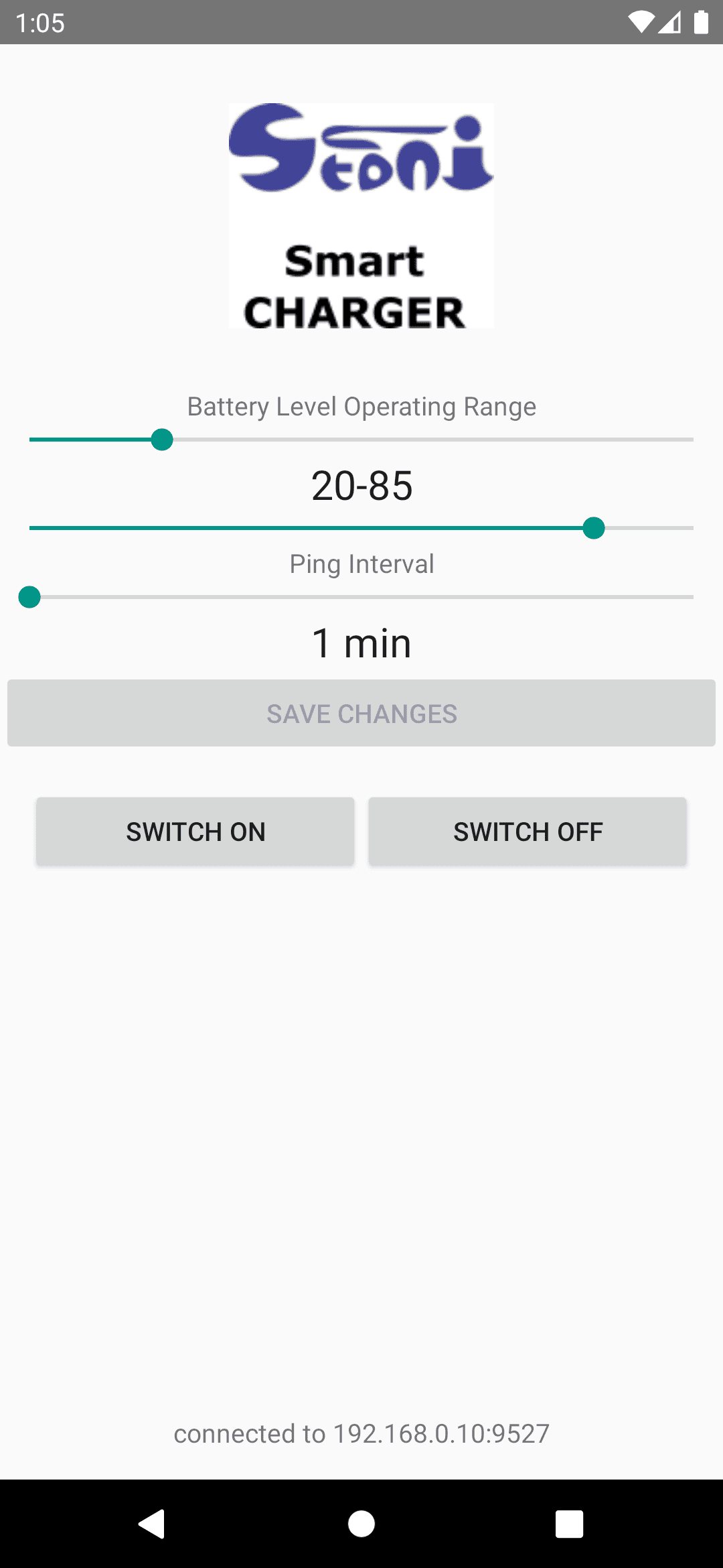
The user interface features two sliders that define the upper and lower limits of the battery charge level operating range.
he lower limit slider indicates that the charger will always be ON when the battery level falls below this value.
The upper limit slider indicates that the charger will always be OFF when the battery level exceeds this value.
Additionally, there is a third slider that sets the ping interval in minutes, determining how often the phone reports its status to the server.
A ping timeout occurs if the server does not receive a status update for 2.5 ping intervals.
Commands to switch the charger ON or OFF are sent via the server. When the button is clicked, an appropriate command is sent to the server, which then executes it by sending the correct RF code.
A foreground service is initiated during the first run. This type of service in Android is designed to operate for an extended period.
The Android system is known for quietly terminating background services when it detects a shortage of memory or other resources.
However, a foreground service must maintain a notification in the notification area of your phone as long as it is active.
The service periodically checks the battery level (according to the ping interval set earlier) and reports this information to the server.